
- Elektromos eszköz ki-/bekapcsolását képes elvégezni
- Kompakt méret
- A kimenet névleges árama: 15A
- Mobiltelefonról is vezérelhető
- Méretek: 40 x 44 x 20 mm
- 60mm-nél nagyobb fali dobozba szerelhető
Aeotec Nano Switch.
Aeotec Nano Switch has been crafted to power connected sockets and switches using Z-Wave Plus. It is powered by Aeotec’s Gen5 technology.
To see whether Nano Switch is known to be compatible with your Z-Wave system or not, please reference our Z-Wave gateway comparison listing. The technical specifications of Nano Switch can be viewed at that link.
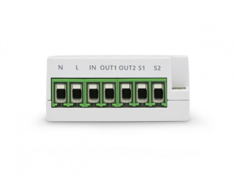
Familiarize yourself with your Nano Switch.


L – Power input for live
N – Power input for neutral
IN – Input for load power supply type (ie. if 120VAC is connected to IN, then OUT will output 120VAC to the load)
OUT – Output for load (This is directly connected to your Loads input to receive power).
S1 – External switch control for load
S2 – External switch control for load
Important safety information.
Please read this and other device guides carefully.The failure to follow the recommendations set forth by Aeotec Limited may be dangerous or cause a violation of the law. The manufacturer, importer, distributor, and / or reseller will not be held responsible for any loss or damage resulting from not following any instructions in this guide or in other materials.
Keep product away from open flames and extreme heat. Avoid direct sun light or heat exposure.
110/120 volt editions of Nano Switch cannot exceed 15 amps. 220/230/240 volt editions should not exceed 10 amps.
Install the Nano Switch.
Nano Switch installs behind a lighting switch or a momentary push button. It works with only 3-wire (with neutral) lighting setups, though each installation of Nano Switch is accordingly slightly different:
1. Shut off the main circuit breaker of your home for safety during the installation and ensure the wires are not short circuited during the installation which will cause damage to the Nano Switch.
Note: Your home’s main circuit breaker must support the overload protection for safety.

2. Preparing connection wires
14 AWG power wires for Input / Output.
18 AWG copper wires for external manual switch.
Use the wire stripper cut the metallic part of the connection wire and make sure the length of the metallic part is about 5mm.

Note: All connection wires needs to be flexible cable.
Wiring diagram of 120/230VAC power input.


Note: The “IN” terminal should be connected to the “-” of 24VDC input.
Warning: Nano Switch ZW116 is not compatible with this configuration, you must use Nano Switch ZW139 without energy reading.
Wiring diagram of 24VDC power input.
Since the Nano Switch also supports the 24VDC power input, so you can use it to control the loads that powered by 24VDC.


Warning: Nano Switch ZW116 is not compatible with this configuration, you must use Nano Switch ZW139 without energy reading.
All above wiring diagrams show that the Nano Switch uses 2-Way or momentary button switches as the external manual switch for 2-Way connection.
The below diagram will show you that the Nano Switch uses the SPDT (Single-Pole Double-Throw) switches as the external manual switch for 3-Way connection.
Wiring diagram of 3-Way connection for the external manual switch.

3. Install Nano Switch to the gang box.
a. Live/Hot wire connection: Connect the Live/Hot wire to the “L” terminal on the Nano Switch.
b. Neutral wire connection: Connect the Neutral wire to the “N” terminal on the Nano Switch.
c. Load wire connection: Connect the Load wire to the “OUT” on the Nano Switch.
d. External/manual Switch connection: Connect 2 18AWG wires to the “S1” and “S2” on the Nano Switch.
e. External/manual Switch connection: Connect 2 18AWG wires form the 2 terminals on the External/manual Switch to the Live wire.

Note: This is the physical connection diagram for 120/230VAC power input.
4. Mounting the gang box.
1. Position all wires to provide room for the device. Place the Nano Switch inside the gang box towards the back of the box.
2. Position the antenna towards the back of the box, away from all other wiring.
3. Reinstall the Nano Switch to the gang box.
4. Reinstall the cover onto the gang box.

2. Use flexible copper conductors only.
5. Restore Power.
Restore power at the circuit breaker or fuse.

Quick Start.
Adding your Nano Switch to a Z-Wave network.
After your Nano Switch is installed and powered on, you are now able to manually control the Nano Switch to turn it On/Off directly via pressing your Nano Switch’s Action Button, it is now time to add your Nano Switch to the Z-Wave network. To set your Z-Wave gateway/controller into pairing mode, please refer to the respective section within your controller instruction manual.
1. Set your Z-Wave controller into pairing mode.
2. Press the Action Button on the Nano Switch once or toggle the external manual switch once, the green LED (non-secure indication) will blink to indicate the Nano Switch is entering into pairing mode.
3. If the Nano Switch has been successfully added to your Z-Wave network, its RGB LED will be solid. If the pairing was unsuccessful, the red LED will be on for 2 seconds and then remain a colorful gradient. Repeat the instructions above
from step 1.
With your Nano Switch now working as a part of your smart home, you’ll be able to configure it from your home control software/phone application. Please refer to your software or gateway user guide for further instructions on configuring Nano Switch to your needs.
The colour of RGB LED will change according to the output load power level:
| Version | LED indication | Output (A) |
| US | Green | [0A, 7.5A) |
| Yellow | [7.5A, 13.5A) | |
| Red | [13.5A, 15.5A) | |
| AU | Green | [0A, 5A) |
| Yellow | [5A, 9A) | |
| Red | [9A, 10.5A) | |
| EU | Green | [0A, 5A) |
| Yellow | [5A, 9A) | |
| Red | [9A, 10.5A) |
Removing Nano Switch from a Z-Wave network.
Your Nano Switch can be removed from your Z-Wave network at any time. You’ll need to use your Z-Wave network’s main controller. To set your Z-Wave controller/gateway into removal mode, please refer to the respective section within your controller instruction manual.
1. Set your Z-Wave controller into removal mode.
2. Press the Action Button on the Nano Switch once or toggle the external manual switch 3 times in fast succession.
3. if the Nano Switch has been successfully removed from your Z-Wave network, its RGB LED will remain colourful gradient. If the removal was unsuccessful, the RGB LED will still be solid (following the state of the output load), repeat the instructions above from step 1.
